Cell Testing
PEC offers a wide range of cell testers, starting from the 5A desktop test system (ACT0505), to our range of 50A cell testers for more standardized cycling (CT0550) and our advanced cell testers with capabilities up to 4000A (ACT0550). All systems support parallel switching for achieving higher currents.
Module Testing
This product range offers 45V, 100V and 150V systems, with a 60A per channel capability. All systems support parallel switching for achieving higher currents. Each channel has an onboard CAN-bus connection for BMS interfacing and can be extended with auxiliary IO’s for single cell voltage and temperature measurements.
Pack Testing
PEC offers a 600V-600A and a 1000V-500A system with either 1 or 2 channels. The systems are programmable using the standard PEC LifeTest application, offering a user-friendly environment for configuring and analyzing drive cycles and other energy storage simulations.
LifeTest Software
In combination with the extended range of PEC test equipment, LifeTest supports the many specific functionalities required in battery testing labs. Drive cycle simulations (FUDS, DST…), thermal performance tests, high speed pulse tests (HPPT), life cycle tests, accelerated ageing tests and internal resistance measurement tests can be easily configured, scheduled, executed and reported from a single platform.
From µA to 4000A
PEC offers cell and module testers ranging from low power desktop and rack mount cell testers all the way up to high power test systems for cells and modules. All systems are based on linear technology offering excellent dynamics and precision. Systems are typically used in R&D, product evaluation, life cycle testing and end-of-line testing.
Drive Cycle Testing
The software allows end users to download and run pre-recorded CSV files on the test channels. This way the system can simulate complex load patterns found in xEV applications, smart grids…
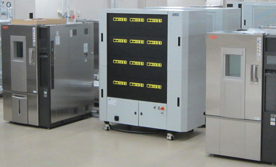
Climate Chamber Control
Most commonly used climate chambers in the battery industry are directly controlled from the test channels, not requiring any third party software interface.
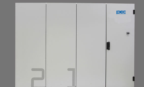
No Heat, no Noise in the Lab
A major challenge in high power test systems is the thermal management of the equipment. Over the years PEC has used its vast experience in water-cooled power electronics to eliminate all unnecessary fans and implement an internal cooling system for the power electronics. This innovative cooling technique was introduced a few years ago in PEC’s cell formation towers. The same platform has now been standardized at PEC and will be used as the basis for all new PEC test systems. As an immediate effect of this high performance cooling platform the test systems will turn your cell testing lab back into area without heat and noise pollution. The improved cooling and elimination of external fans easily doubles the MTBF of the equipment, eliminates filter replacement and dust collection inside the power electronics.
Precision and Speed
In terms of precision and speed PEC has raised the bar on its latest product releases, with 100 µsec based internal sampling, control and capacity calculations, hardware controls for both current and voltage* and a ± 0.005% FSD accuracy on the voltage readings*. All PEC systems have best-in-class features on board, such as 2, 3 or 4 automatically switched current ranges, ±0.03% FSD current control, better than 1 msec rise times, including range and mode switching transitions… * On specific models only
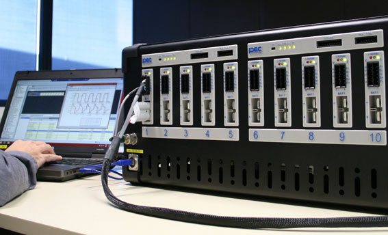
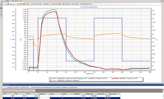
Auxiliary Measurements
Most PEC systems offer an onboard temperature sensor per test channel. However this can easily be extended using our Auxiliary IO’s, offering analog and digital inputs, outputs, thermocouple inputs, NTC/PTC inputs, as well as BMS interface cards. All data collected from the IO’s can be used in your test programs, and outputs can also be set from the software.
BMS Integration
The Auxiliary IO’s offer a powerful platform for creating interfaces to your BMS system’s controllers over either CANbus, SMBus, RS485, USB… Customer specific interfaces can be offered on request. Datapoints can be set and collected over this interface and used in the test programs.